

Digital dockyard system
Digital shipyards are one of the important means to achieve lean shipbuilding. Some large shipyards in South Korea and China (such as Dalian Shipbuilding Industry Co., Ltd. and Jiangnan Changxing Shipbuilding Co., Ltd.) have fully established digital shipyards. By making full use of existing software systems such as IN-CHECK, IN-ANALY, GeoYard digital benchmark measurement and control network management software, Adjust3D three-dimensional network adjustment software, and total stations, they have achieved rapid assembly of block sections in the shipyard, semi-ship displacement, and simulated assembly, significantly improving crane utilization efficiency, shortening shipyard cycle, and thus improving economic benefits and production efficiency.
I. Overview of Digital Dry Dock
Digital dry docks are one of the important means to achieve lean shipbuilding. Some large shipyards in South Korea and China (Dalian Heavy Industry, Jiangnan Changxing, etc.) have fully established digital dry docks. By fully utilizing existing software systems such as IN-CHECK, IN-ANALY, GeoYard digital benchmark measurement control network management software, Adjust3D three-dimensional network adjustment software, and total stations, they achieve rapid assembly of segments in the dry dock, half-ship displacement, and simulation assembly, significantly improving crane utilization efficiency and shortening the dry dock cycle, thus improving economic benefits and production efficiency.
II. Principle of Digital Dry Dock
The principle of a digital dry dock is to establish benchmark targets around the dry dock, recording the original ship's centerline, rib lines, and height datum lines in the dry dock to form a unified dry dock coordinate system. The digital dry dock forms a three-dimensional spatial coordinate system in the dry dock area by erecting digital rotating targets around the dry dock. After the ship enters the dry dock, the position and coordinates are determined according to the position of the first reference segment in the three-dimensional spatial coordinate system; and the segment assembly positioning operation is performed based on the three-dimensional spatial coordinate system formed by the digital rotating targets around the dock wall. By simulating traditional dry dock assembly and positioning operations in advance on the computer, eliminating dry dock grid lines, and achieving rapid segment positioning, zero-clearance assembly, and one-time positioning, it aims to save time, improve crane utilization efficiency, and shorten the dry dock cycle.
III. Construction Process of Digital Dry Dock
3.1 Deployment of Digital Dry Dock Targets
Determine the number and placement distance of control network targets based on the size of the dry dock; digital targets are erected around the dry dock and can rotate 360°; the measurement accuracy of targets is within 2mm per 50m; ensure the verticality of the digital targets during installation.
3.2 Setting Out of Base Lines in the Dry Dock
Refer to the precision management chart and baseline precision table to set out baselines (centerline, large joint line, rib line, longitudinal girder line, auxiliary centerline), strictly adding the precision design allowance. The straightness precision of the centerline is within ±1mm; the inter-position spacing precision is within ±3mm; the longitudinal girder half-width deviation is within ±3mm; the actual deviation from the theory after adding the large joint is within ±2mm; and the base height point deviation is within 2mm.
3.3 Establishment of Des File Coordinates
1. Data Acquisition
Measure the dry dock baselines (centerline, large joint line, 0 rib line, base height point), and use a total station to measure two benchmark points before sequentially collecting the point coordinates of each rotating target. (Note: The selection of benchmark points needs to consider that the benchmark points should be within the visible range when correcting the targets later).
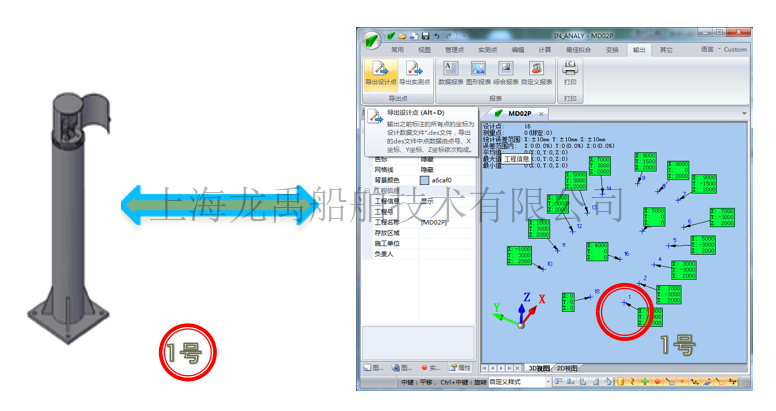
2. Establishing the Original Des File
Import the collected point coordinates of each rotating target into the computer analysis software IN-ANALY. Move one benchmark point to its three-dimensional position (X, Y, Z) in the ship's coordinate system to establish a dry dock coordinate system consistent with the ship's coordinate system, number each rotating target (its number must be consistent with the number of the rotating target at the dock edge), and then output and save to establish the original Des file.
3.4 Inspection of the Des File
Use two-point or three-point connection measurement to import the Des file into the total station to inspect the digital targets. When converting, the actual measured points must match the theoretical points, and the displayed deviation must be within ±3mm to be usable. Starting from the 3rd point measurement, inspect all the targets around the dry dock. The deviation between the actual measured point coordinates and the theoretical point coordinates displayed after the coordinate value must not exceed 3mm.
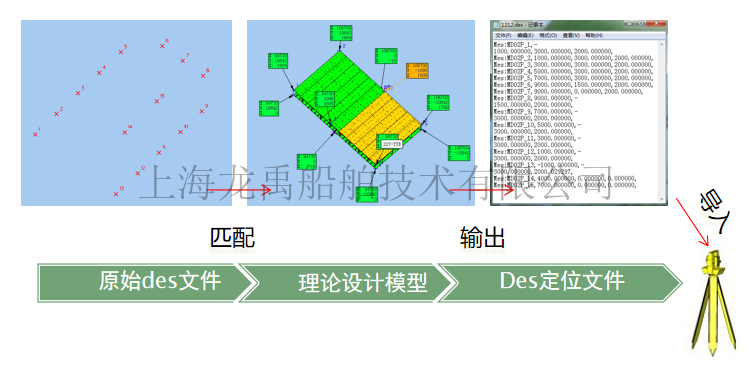
3.5 Establishment of Des File for Assembly and Positioning Segments
Before segment positioning, a matching Des positioning file must be established. First, import the original Des file, then call up the positioning segment model to establish the main management points required for positioning, and finally output and save to establish the Des positioning file. Import the assembly positioning Des file into the total station, perform two-point or three-point connection measurement on the digital dry dock, and assemble the segments.
IV. Application of Digital Dry Dock
4.1 Shipbuilding Planning in Dry Dock
Based on the principle of the digital dry dock and the three-dimensional spatial coordinate system of the digital dry dock, the shipbuilding area can be quickly planned (for example, the types of ships that can be built in the dry dock, how ships are placed and arranged, etc., can be foreseen on the computer) and the shipbuilding dry dock assembly base can be arranged. At the same time, it can complete external (ship owners, ship inspectors) reporting with high precision and high efficiency.
4.2 Application of Rapid Assembly of Dry Dock Segments
Using two-point connection measurement, import the original control network file. When converting, the actual measured points must match the theoretical points, and the displayed deviation must be within ±3mm to be usable. After the conversion, starting from the 3rd point measurement, the deviation between the actual measured point coordinates and the theoretical point coordinates can be displayed after the coordinate value. (Affix reflectors to the important management points of the positioning segment).
4.3 Digital dry docks are more convenient for half-ship floating displacement positioning.
Before half-ship floating displacement, affix 2 reflecting targets to the ship's hull and determine their three-dimensional coordinates (X, Y, Z) in the ship's hull; after displacement, use the three-dimensional coordinates of these 2 points on the ship's hull to determine the ship's coordinates of the rotating targets at the dock edge, establishing a three-dimensional coordinate system consistent with the ship's hull.
4.4 Application of Digital Dry Docks in Simulated Assembly
During the simulation assembly process, use the digital control network to collect data and simulate the pre-assembly of the assembled segments, achieving zero-clearance assembly and one-time positioning of the total segments.
4.5 Measurement and Reporting of Ship's Main Dimensions
Traditional main dimension measurement is based on the original dry dock baselines, using plumb bobs and measuring tapes, and obtaining results through calculations. This is cumbersome and inaccurate. Digital dry docks use the three-dimensional spatial coordinate system established based on the original precision rotating targets, measuring with a total station and transforming to the ship's three-dimensional spatial coordinate system. The positions of the length between two columns, total length, molded breadth, and molded depth are measured to accurately and easily collect data and obtain the required data, enabling high-precision and high-efficiency external reporting.
4.6 Precise Control of Ship Propulsion System and External Reporting of Centering
Following the principles and framework of the digital dry dock, and using a three-dimensional coordinate system, the arrangement of the rudder system reference points can be precise and rapid, simplifying and improving the accuracy of the external inspection and acceptance process.
4.7 Waterline draft, load line, load line marks, etc., marking and inspection
Following the principles and framework of the digital dry dock, and using a three-dimensional coordinate system, using a total station instrument to measure through a reference rotating target and entering the waterline draft measurement mode, the location of the waterline draft can be accurately and quickly found, and points can be marked and lines drawn. After the waterline draft construction is completed, the same method is used for external inspection and acceptance.
V. Post-operation Management and Maintenance of Digital Dry Dock
5.1 Management and Maintenance of Digital Benchmark Points
Control network benchmark points are divided into two types: visible and hidden points. For visible points, protective devices are installed above the ground and warning signs are provided. For hidden points, a high-precision restoration mechanism is designed to facilitate the disassembly and installation of points. Damaged benchmark points need to be replaced. After replacement, the benchmark points need to be re-measured. For benchmark points that are retained, accuracy verification is required. They can continue to be used after meeting the accuracy requirements.
5.2 Stability Observation
Given that the site will undergo settlement and deformation during the process from empty load to full load, and over time, this will affect the accuracy measurement control network benchmark point data. At the beginning of the construction of the precision measurement control network, the dry dock is monitored for settlement, which is used for dry dock stability analysis and the design of the precision measurement control network data correction scheme.
Stability observation uses the single-station polar coordinate method, and measurements are performed using both total station instruments and laser trackers to establish initial deformation data.
5.3 Dry Dock Database Reliability Test and Review
Data reliability self-checking mechanisms are incorporated into all digital dry dock usage schemes to facilitate the timely detection of benchmark point position changes during use and ensure the smooth implementation of segmented positioning and loading. After a period of operation, especially when some benchmark points are damaged, the digital dry dock database can be re-measured to check its accuracy and reliability.
VI. Future Development Direction
The digital dry dock is upgraded to a three-dimensional digital measurement system, which is shared by the hull, machinery, and outfitting. Various existing measuring instruments and construction equipment, such as laser trackers, laser levels, scanners, total stations, three-dimensional adjustment trolleys, and hydraulic synchronous lifting devices, share this three-dimensional network data to achieve integrated, rapid measurement, closing, positioning, and loading of any module at any location. This becomes one of the important process methods of intelligent shipbuilding on a big data platform. At the same time, the three-dimensional digital measurement system is one of the important cornerstones of future information-based shipbuilding and one of the important data sources for future database analysis.
Company Address: Room 201, Building 11, No. 299, Bisheng Road, Pudong New District, Shanghai
Company Telephone:021-33830252
Company Fax: 021-33830253
Company Postcode: 201204
Company Email:service@shipac.com.cn